Brainstorm SR-112 Timecode Distripalyzer
1 x 12 DISTRIBUTOR / RESHAPER
- Designed to send clean time code over long cables
- Eliminates level fluctuations
- Buffered outputs; balanced or unbalanced
TIME CODE ANALYZER
- Identifies time code format, reports errors (drop outs…)
- Monitors video phase
- Generates a comprehensive report via Ethernet
TIME CODE GENERATOR (option)
- Generates new time code with or without video reference
- Repairs faulty time code (jam sync)
TIME CODE ANALYZER
Eliminates frustrations and downtime by identifying quickly and accurately errors with a powerful time code analyzer:
• Time code format & Frame Rate:
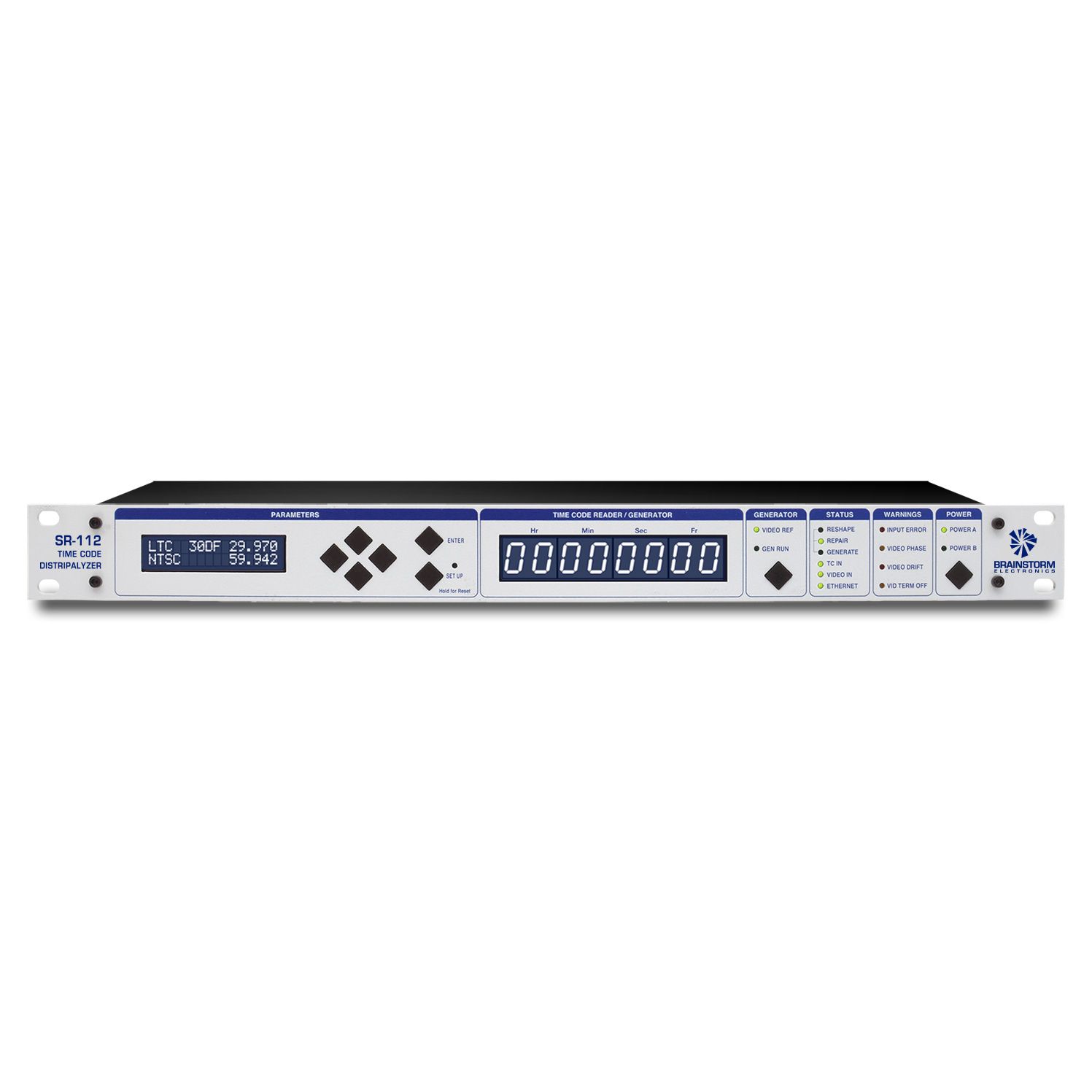
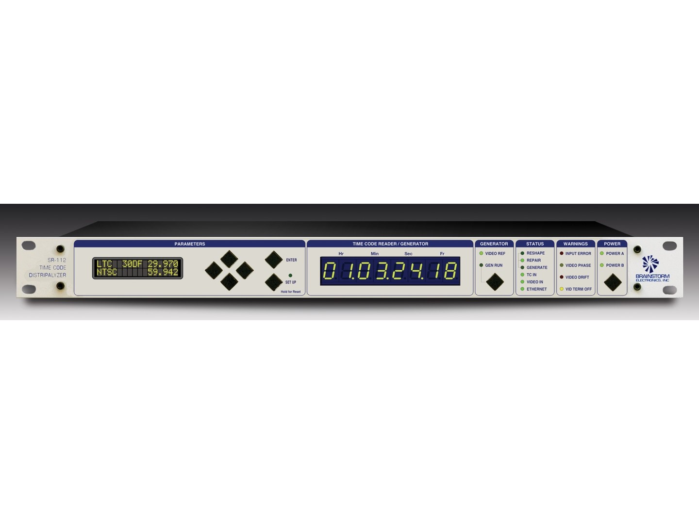
The front panel displays separately the format (24, 25 or 30), the drop frame status and the frame rate of the incoming time code.
For example: 30 drop at a rate of 29.97. No more guessing!
In addition, the frame rate counter can show potential problems such as jitter or wow and flutter.
• Time code errors:
Time code errors such as repeated frames, drop outs etc. are detected and reported on the front panel along with the faulty addresses. A buzzer sounds whenever the analyzer detects an error.
• Video Phase:
In post production, it is essential that time code be synchronous with video (i.e. the video frame must be perfectly aligned with the corresponding time code word). The SR-112 accurately monitors the phase between time code and video and reports even slow drifts.
• Time code report:
A comprehensive report that includes format, video phase and time code errors can be sent to a computer via the rear panel Ethernet port.
DISTRIBUTOR/ RESHAPER
While analyzing, the SR-112 distributes and reshapes time code through a 1×12 distributor:
• Buffered outputs:
The 12 time code outputs are balanced and buffered, avoiding the problems caused by multing a single source.
• Output Levels:
Output levels are adjustable individually via the Output Level menus. Since the signal is reshaped, output levels remain constant, regardless of the input level.
• Reshaping:
The Brainstorm Time Code Distributors are more than audio DA’s: they reshape the signal before distributing it. By reshaping the signal, the SR-112 eliminates amplitude distortions and input level fluctuations.
TIME CODE GENERATOR – OPTIONAL SOFTWARE: TCG
An optional software (TCG) can be purchased that adds a time generator module to the SR-112. This TGC has 2 main functions: Repairing time code and generating new time code.
• Repairing Time Code:
In REPAIR mode, the SR-112 fixes drop outs by regenerating the incoming code (jam-sync). It can also correct video phase when it is missaligned.
• Generating new Time Code:
In GENERATE mode, the SR-112 generates new time code. Start time, format and frame rate can be set. The generator can also be genlocked to external video.
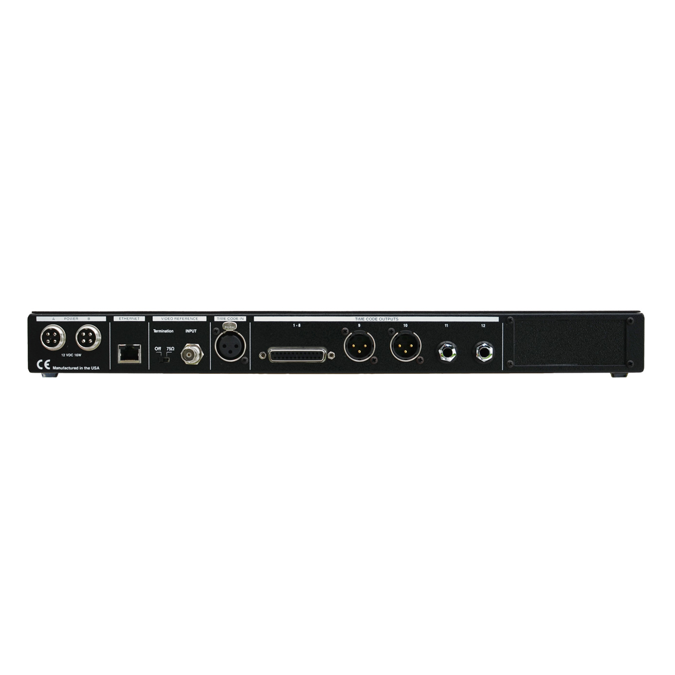
| Distributor Configuration | 1×12: 1 x DB-25 F (8 outputs – Tascam/Avid analog pin configuration), 2 x XLR M, 2 x 1/4″ TRS | ||
| Input Signal | SMPTE/EBU Longitudinal Time Code Impedance: 20KΩ bal.; 10KΩ unbal. Level: -30dbU min; +20dbU Max | ||
| Output Signal: | Waveform: switchable rise time: 1us (square); 25us (SMPTE); 50us (EBU) Impedance: 600Ω bal.; 300Ω unbal. Level: adjustable: full off to +8dbU bal.; to + 2dbU unbal. Amplitude distortion: less than 2% | ||
| Status LEDs: | Reshape Repair (TCG option) | Generate (TCG option) TC In | Video In Ethernet |
| Warning LEDs: | Input Error (red) Video Phase (yellow) | Video Drift (red) Video Termination Off (yellow) | |
| Time Code Reader: | The 8 digit LED Display indicates hours, minutes, seconds and frames. The display also flashes error descriptions when detected. | ||
| LCD Display: | In addition to being used for SET UP, the 32 carachter LCD display indicates the following: – Format and rate of the incoming time code – Format and rate of the video reference – User Bits – Video Phase – List of errors | ||
| Connectors: | Time Code in: XLR Female (x 1) Video Ref: BNC (x 1) Time Code outputs: – DB25 (1x) – Tascam/Avid analog pin configuration: outputs 1-8; – XLR Male (2x): outputs 9-10; – 1/4″ jacks (2x) – TRS: outputs 11-12 Ethernet: RJ45 jack (x 1) Power: 4 pin circular (x 2) | ||
| Power: | 12VDC @ 5A Redundancy: two separate supplies can be connected to the 2 separate power inputs. If one supply fails, the other takes over and an error is reported. The faulty supply can be swapped without having to power down. | ||
| Dimensions: | 19” x 8.125” x 1.75” (48.26 cm x 20.64 cm x 4.45cm) | ||


